Hello, optical friends!
In the field of aspheric surface testing, we’ve previously introduced some conventional interferometric methods. However, when dealing with complex surfaces with high curvature and large deviations, traditional methods fall short. Today, let’s dive deeper into a more advanced and precise technology — the combination of interferometer and CGH (Computer Generated Hologram) testing. This is not only the ace technology of modern optical testing but also the authoritative method for measuring ultra-high precision aspheric and freeform surfaces.
To understand the value of CGH, we first need to understand the limitations of traditional interferometers.
The Bottleneck of Traditional Interferometers:
Traditional interferometers use standard spherical or planar reference wavefronts. They can only measure surfaces that closely resemble the reference wavefront. When light strikes an aspheric surface, the reflected wavefront deviates significantly from the reference wavefront, causing the interference fringes to become overly dense or even impossible to discern. The measurement fails.
CGH’s "Genius Move":
CGH is essentially a digital "wavefront reshaper." Its core mission is to precisely “transform” the perfect spherical wave emitted by the interferometer into a custom wavefront that exactly matches the theoretical shape of the aspheric surface being measured.
The brilliance of this process lies in the fact that when this custom wavefront illuminates an ideal, error-free aspheric surface, the light will return along the same path and, after passing through the CGH again, be restored to a perfect spherical wave. At this point, it perfectly matches the reference wavefront, and the interference field presents a uniform "null field" (almost no fringes). Any small surface shape deviation will disturb this perfection, generating clear and quantifiable interference fringes. In short, CGH cleverly "tricks" the interferometer into measuring the aspheric surface "as if" it were a standard spherical surface, enabling nanoscale high precision.
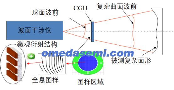
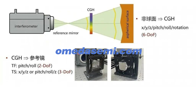
A complete interferometer + CGH testing system consists of three main core components:
High-Precision Phase-Shifting Interferometer:
Provides a stable laser light source and reference optical path, and is responsible for capturing, phase-shifting, and solving the interference patterns. It is the "brain" and "eyes" of the system.
Computer Generated Hologram (CGH):
This is the soul of the system. It is a micro-optical element made on a glass substrate using photolithography or electron beam etching technology, with precision binary relief structures on its surface. Its main functions include:
(1) Wavefront Generation: Converts the incident spherical wave into the ideal aspheric wavefront via a +1 diffraction order.
(2) Integrated Alignment Function: Advanced CGHs also integrate holographic alignment elements (HAE), which can project a bright alignment spot, greatly simplifying and precisely calibrating the adjustment process.
High-Stability Precision Adjustment Frame:
Used to support and fine-tune the aspheric component under test. Its precision and stability directly relate to the reliability of the final results because micron-level positioning errors can lead to significant measurement errors.
Step 1: CGH Design (Core Preparation)
This is the most critical preparatory step. Based on the accurate mathematical model of the aspheric surface, interferometer parameters, and relative layout, professional optical design software (such as Zemax, Code V) is used for reverse calculation to generate the phase distribution data of the CGH, which is then sent to a professional manufacturer for fabrication. This step determines the success or failure and the precision limit of the test.
Step 2: System Setup and Precision Alignment (Biggest Challenge)
This is the most difficult and key part of the actual operation.
(1) Building the Optical Path: The interferometer, CGH, and the tested component are initially installed in their designed positions.
(2) HAE Precision Alignment: By adjusting the position and orientation of the tested component, the alignment spot generated by the HAE on the CGH is precisely moved to the predetermined reference position. This step minimizes system setup errors, laying the foundation for obtaining accurate data.
Step 3: Data Collection
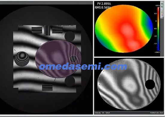
Once alignment is complete, the interferometer’s camera captures multiple interference images generated by phase-shifting techniques. These images contain all the information about the surface shape deviations of the component under test.
Step 4: Data Processing and Error Correction (Shows Professionalism)
Raw data cannot be used directly; it must undergo rigorous error separation and correction:
Phase Calculation: The phase map representing surface shape deviations is derived from the phase-shifted interference images.
System Error Deduction:
(1) Intrinsic CGH Errors: Errors caused by imperfect CGH fabrication, which need to be calibrated with high precision (e.g., using Atomic Force Microscopy) and subtracted.
(2) Residual Alignment Errors: Small deviations remaining after precise alignment, which are calculated and deducted through modeling.
(3) Interferometer System Aberrations: Optical errors in the interferometer itself must be calibrated and deducted in advance.
Results Output: The final output is a clean surface map that reflects the true manufacturing deviations of the aspheric surface. This is typically evaluated quantitatively using PV (peak-to-valley) and RMS (root-mean-square) values and can generate intuitive 2D/3D cloud maps.
Significant Advantages:
(1) Ultra-High Precision: One of the highest precision methods for measuring complex aspheric surfaces, with accuracy up to λ/100 RMS or even higher (sub-nanometer level).
(2) Extreme Flexibility: As long as the mathematical model is clear, theoretically any shape of aspheric or freeform surface can be measured.
(3) Powerful Functionality: The integrated HAE simplifies and improves the alignment process, reducing human error.
Challenges Not to Be Overlooked:
(1) High Cost: CGH design and fabrication are expensive, especially for large-aperture, high-precision components.
(2) Long Cycle: From design to obtaining a usable CGH typically takes several weeks to months.
(3) Strong Specialization: A CGH is usually designed for a specific component and optical path layout, lacking generality.
(4) High Operational Requirements: The setup precision and the operator’s experience are crucial.
In conclusion, the interferometer + CGH method is a cutting-edge optical testing technology based on the precise "null compensation" principle. By using CGH's digital wavefront modulation capability, it transforms the measurement of complex aspheric surfaces into highly sensitive null-field interference measurements, achieving unparalleled precision. Despite challenges in cost and cycle time, it remains an irreplaceable "ultimate solution" when facing the most demanding testing requirements.
High‑precision CGH design and fabrication — please contact Shanghai Omeda: https://www.omedasemi.com
OMeda (Shanghai Omedasemi Co.,Ltd) was founded in 2021 by 3 doctors with more than 10 years of experience in nanpfabrication. It currently has 15 employees and has rich experience in nanofabrication (coating, lithography, etching, two-photon printing, bonding) and other processes. We support nanofabrication of 4/6/8-inch wafers.